This week I… Built a Xino Basic for Atmel as sold on http://shop.ciseco.co.uk
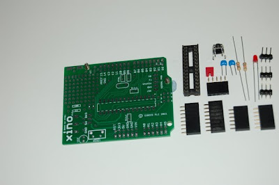
This is sold as a kit that anyone with even the most basic of soldering skills can put together. This is just about the cheapest way to get an Arduino compatible board that fits the standard Arduino shields. It also boasts a nice little prototyping area at the top which will mean that a lot of smaller projects can be completed without the need for additional shields. (See my Xino Dice post for an example of how the prototyping area can be used)The main kit comprises of the PCB, processor socket, connector headers and some resistors, capacitors and an LED
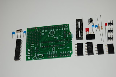
If you already have an Atmel ATMEGA328 processor, a couple of 22pf capacitors and a 16Mhz crystal then you’re good to go. But if not, you can buy these components from many online resellers, including, of course, Ciseco. The ones Ciseco supply come in two flavours; Uno bootloader or Duemilanove bootloader pre-programmed. They are physically the same, the difference being which bootloader is programmed, which will affect which board you need to select in the Arduino IDE.
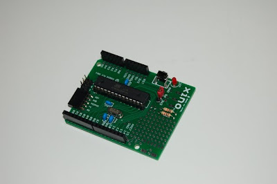
The components need to be soldered on to the PCB. Assuming you have basic soldering skills this shouldn’t take more than about 5 – 10 minutes. Like most boards you will want to start with the components closest to the board (resistors, caps), and work up to the tallest ones (the shield headers). One useful tip to get the shield headers strait is to plug them in to a spare shield first, then slide the PCB on to the pins and solder them with the shield in place. The LED needs to be fitted with the negative (shorter lead, flat side) closest to the outside of the board, and the processor socket with the indentation notch furthest away from the resistors. You should end up with something that looks like this;
Unlike the Arduino Uno, the Xino does not come with a USB programming interface. Instead it has a simpler FTDI style serial interface. This allows multiple ways of programming the Xino. Depending on what you already have lying around some of the options are;
* Use an Arduino Uno (or compatible) board to program the processor, then remove it and plug it in to the Xino
* Use an FTDI cable and a 6 pin to 5 pin adapter. I made this one for the Xino dice project. You can make your own like this, use a bit of Veroboard or buy a ready made one.

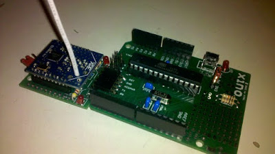
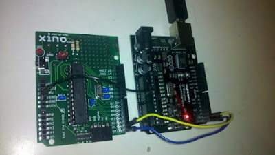
* Use an Arduino (or compatible) as the USB host and connect over to the Xino. You will need to connect ground, Tx and Rx on one board to the same connectors on the other board. Either use jumper cables as shown below, or make a programming interface board as (Link to follow). Remove the processor from the host and hit the reset button just the ‘Binary sketch size:’ message shows on the IDE notification area.
* Wirelessly program the Xino with a XRF and an XBee Breakout Board. Instructions on how to do this will feature in my next blog update.