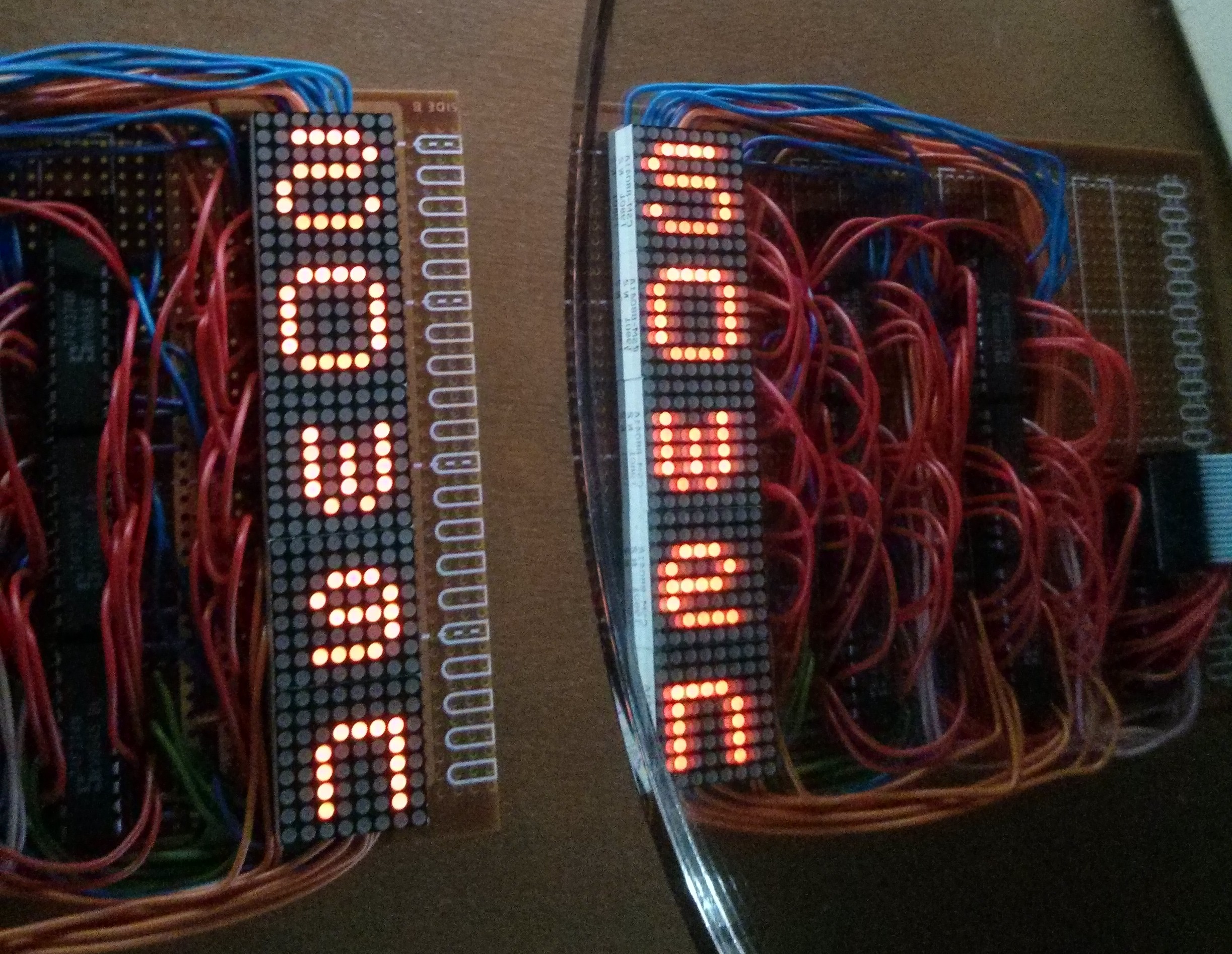
This is one of those little projects that didn't need to be done, or could have been done very simply. Despite a lot of feature creep, everything just came together at the right time, and I'm really pleased with the results.
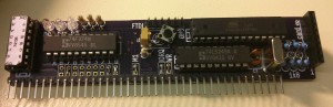
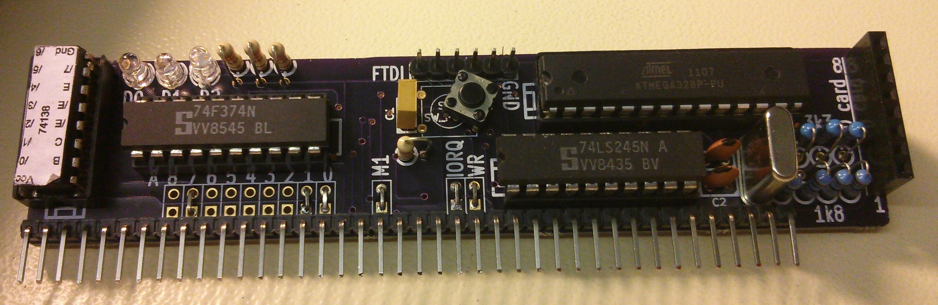
Just a quick update to about the SD Bootloader I designed a few posts ago. Well, the PCBs have arrived and last week I took a soldering iron to one of them and gave it a quick test
One side of the board is effectively an Arduino, so without plugging it in to the RC2014, I connected up an FTDI lead and uploaded the Arduino Blink sketch. A quick check with a multimeter and one of the pins was altenating between 5v and 0v. So far, all good!
With over 24 hours to go before the end of July deadline the final piece of the puzzle fell in to place! But, first, a quick catchup from the last blog post;
Despite a late start today, things have gone well so I actually feel like I'm ahead of the game right now. Certainly not finished, but with most of the major hurdles now behind me, the only thing left is writing a bit of Z80 assembler code. And even that is starting to look manageable.
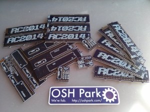
So, exactly 3 weeks after they were ordered, the PCBs from OSHPark arrived today. It's just as well, as I was running low on things to do without them, and with just 6 days left of the Retro Challenge I would have struggled to finish in time. Well, that's my weekend planned out for me now!
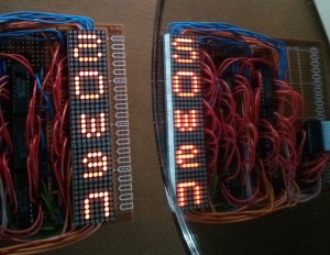
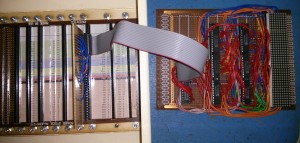
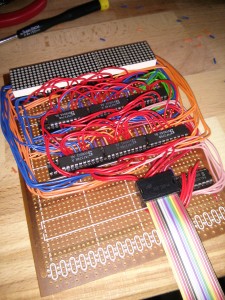
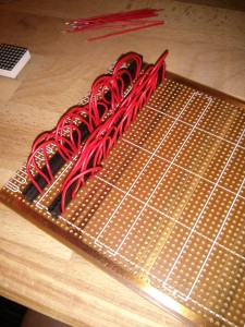
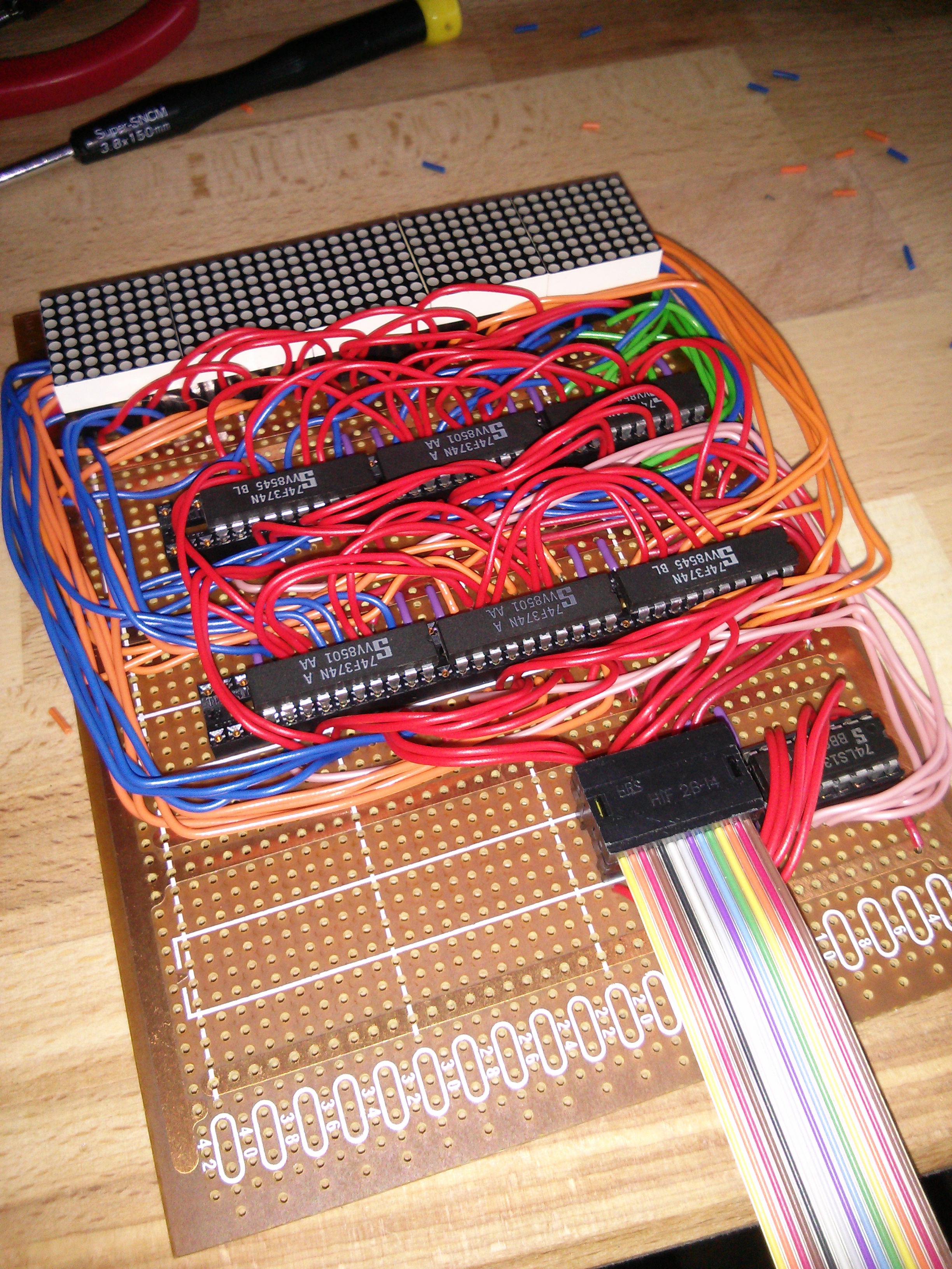
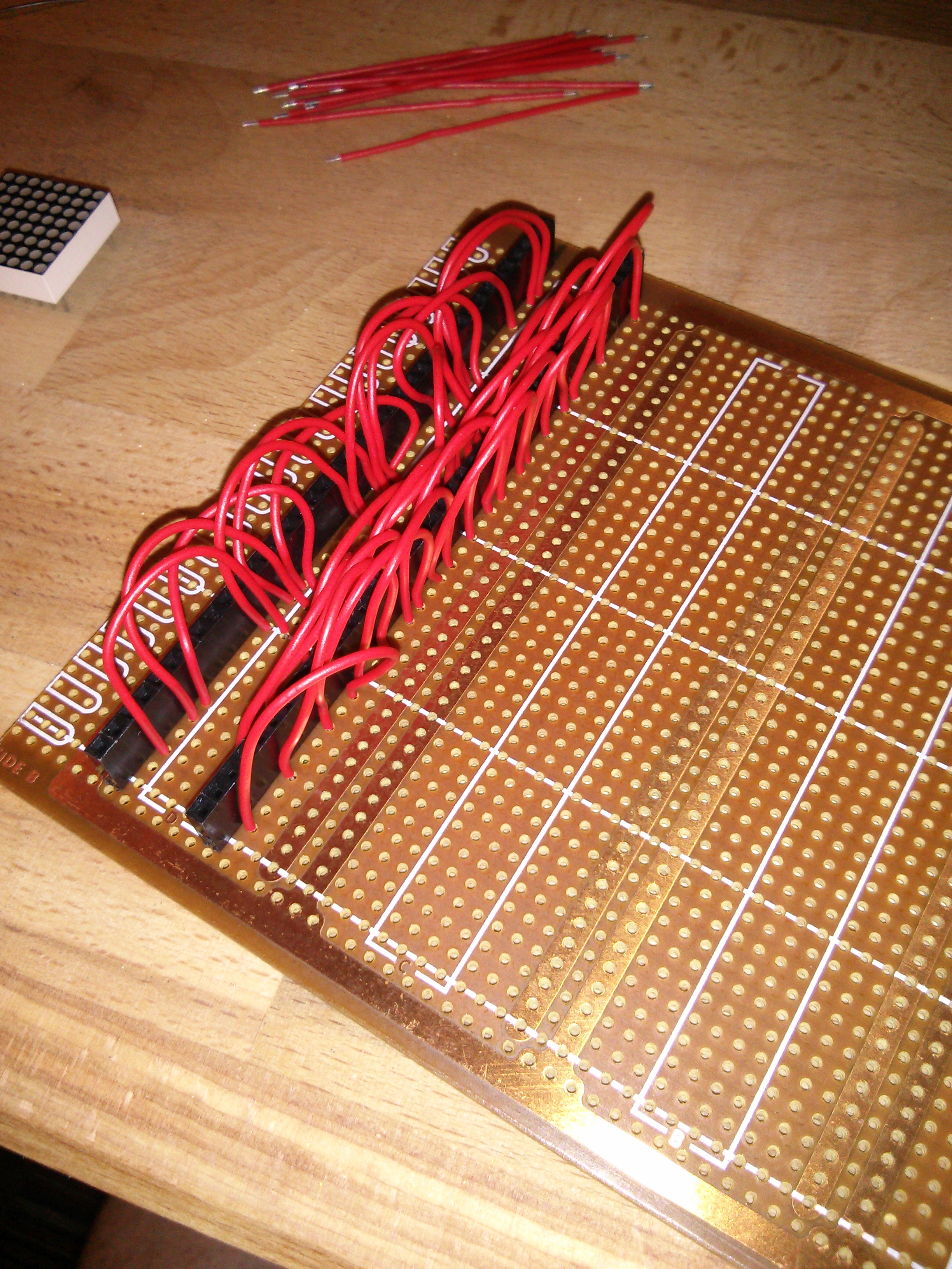
The mounting of the LED matrix has probably caused me the biggest turmoil so far on the Retro Challenge. First, I was going to design a custom PCB for them, but I missed the window of opportunity to get it manufactured at a reasonable price. So, for simplicity, I decided to use breadboard until I realised this wasn't simple with that amount of wires. So, I went back to PCB design preparing to take the financial hit. However, it proved impossible to get the tracks to fit, so this idea went in the bin again. Back to breadboard, I bought a load of jumper cables, and started expanding on what I started earlier. For the driver chips it was ok. For the matrices themselves though, I came across a show stopper; The width of it is so wide that in the breadboard there are 2 free tie points on one side but just 1 on the other. Getting a data bus down all of them was not going to be possible :-( So, I had a rummage through some vintage Veroboard and found a Euro-card sized board with chip layout tracks. It would only fit 5 modules side by side, but I was prepared to make that sacrifice. I also had some 40 pin female sockets, so that made life even easier!